7 Reasons Your Tungsten Carbide Bushing Is Cracking — And How to Stop It
Tungsten carbide is one of the hardest materials used in industrial applications. So when a bushing cracks, the first instinct is to blame the material. Maybe it was a bad batch, or the supplier cut corners. In most cases, though, that assumption is wrong.
Cracking in tungsten carbide bushings is almost always a system problem. The material itself rarely fails spontaneously. What fails is the fit, the installation, the operating conditions, or the grade selection. The bushing is just where the consequences show up.
This article breaks down the 7 most common reasons tungsten carbide bushings crack, what to look for in each case, and what you can actually do to fix it.

Quick Diagnosis: Where Does the Crack Appear?
| Crack Pattern | Most Likely Cause |
| Longitudinal crack, appears within hours of installation | Interference fit too tight |
| Irregular crack, found same day as installation | Improper installation method |
| Repeated cracking in high-impact applications | Wrong carbide grade |
| Edge chipping, always on the same side | Misalignment / uneven load |
| Network of fine surface cracks, surface discoloration | Thermal stress or lubrication failure |
| Micro-cracks only visible under inspection | Grinding burns from manufacturing |
| Multiple bushings failing in the same batch | Overloading / design limit exceeded |
Cause 1: Interference Fit That’s Too Tight
This is the most overlooked cause and one of the most common.
When you press a tungsten carbide bushing into a housing, the housing squeezes the bushing. That squeeze creates hoop stress (a circumferential tensile force) inside the carbide. Tungsten carbide handles compressive loads very well, but its tensile strength is much lower, typically in the range of 700–1,000 MPa depending on grade. If the interference is too aggressive, that hoop stress exceeds what the material can handle, and you get a longitudinal crack running along the length of the bushing.
What to look for: A clean, straight crack running parallel to the bushing axis, appearing within hours or days of installation, sometimes before the machine even starts.
The fix: Recalculate your fit tolerance. For carbide bushings, interference should generally stay conservative. A common starting point for a 50mm OD bushing is 0.03–0.06mm, but this varies by wall thickness and housing material. Use the ISO 286 standard as a reference for hole and shaft tolerances, and consider switching from a press fit to a shrink fit, which distributes stress more evenly during assembly.
Cause 2: Improper Installation Method
Hammering a carbide bushing even with a soft mallet applies a sudden, localized force that the material simply cannot absorb. Unlike steel, which deforms under impact, tungsten carbide fractures. There’s no warning, no deformation, just a crack.
What to look for: An irregular fracture pattern (not a clean straight line), discovered immediately after or on the same day as installation.
The fix:
- Use a hydraulic press with a guide sleeve to ensure the bushing enters the bore on-axis.
- For shrink fit installations, heat the housing to 150–200°C — just enough to expand the bore, not so much that you cause oxidation.
- Before installation, apply a thin coat of engineer’s blue (marking compound) to check that the bore is truly cylindrical. A tapered or out-of-round bore creates uneven contact pressure, even when the nominal fit looks correct.
- Never use an impact hammer on a carbide bushing. Ever.
Cause 3: Wrong Carbide Grade for the Application
Not all tungsten carbide is the same. The grade primarily determined by cobalt (Co) content controls the balance between hardness and toughness.
Low cobalt content (around 6%) gives you maximum hardness and wear resistance, but the material becomes brittle under impact. High cobalt content (around 15%) trades some hardness for significantly better toughness, making it the right choice where shock loads are involved. Using a low-cobalt grade in an application with intermittent impact loading is one of the fastest ways to crack a bushing.
| Grade (Co%) | Hardness (HRA) | Impact Resistance | Best For |
| ~6% Co | 91–92 | Low | Continuous, stable loads; wear-critical |
| ~10% Co | 89–90 | Medium | General-purpose applications |
| ~15% Co | 87–88 | High | Impact loads, mining, stamping |
What to look for: Cracking appears early, especially in applications with vibration, shock, or intermittent loading. The failure often repeats with replacement bushings of the same grade.
The fix: Reassess the actual operating conditions. Not just the steady-state load, but any shock or vibration that occurs during startup, reversal, or material impact. If impact is a factor, move up to a higher cobalt grade. For highly abrasive and high-impact environments simultaneously, composite grades with TiC or TaC additions may offer a better balance.
Cause 4: Misalignment and Uneven Load Distribution
A bushing installed with perfect fit and the right grade can still crack if the shaft running through it isn’t properly aligned.
Misalignment creates a situation where one side of the bushing carries significantly more load than the other. Over time or sometimes immediately, this causes stress concentration at the overloaded edge, leading to chipping or cracking on one side of the bore.
What to look for: Cracking or chipping that consistently appears on the same side of the bushing. Uneven wear on the bore surface is another sign. If you pull a failed bushing and the wear pattern looks asymmetric, misalignment is likely.
The fix:
- After installation, use a dial indicator to check radial runout. For precision applications, aim for ≤0.01mm.
- Inspect the mounting surface for flatness — a slightly warped housing can introduce angular misalignment even when the centerlines look correct.
- Add a lead-in chamfer on the bore entry (15°–30°) to prevent edge loading during shaft insertion and operation.
Cause 5: Thermal Stress and Lubrication Failure
Heat is a silent contributor to bushing failure. When lubrication breaks down or was never adequate to begin with friction generates localized heat at the bushing interface. Tungsten carbide can handle high static temperatures, but rapid temperature cycling causes thermal fatigue, which shows up as a network of fine surface cracks.
At temperatures above 400°C, the cobalt binder phase can begin to oxidize, which accelerates wear and reduces the structural integrity of the bushing.
What to look for: A mesh or network of fine cracks across the bore surface, often accompanied by surface discoloration (darker patches, or a slight blue-gray tint from oxidation). Unlike fit-related cracks, thermal cracks tend to be shallow and distributed rather than singular and deep.
The fix:
- Verify that the lubricant specified for the application is rated for the actual operating temperature range. A grease rated for 120°C isn’t suitable for a spindle running at 200°C ambient.
- For high-speed applications, consider switching from periodic relubrication to a continuous forced lubrication or recirculating oil system.
- Check lubrication intervals. In many maintenance schedules, bushings are among the last items to get attention until something fails.
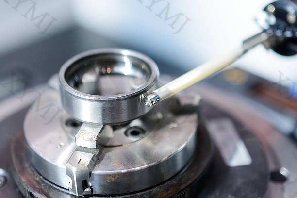
Cause 6: Grinding Burns from the Manufacturing Process
Tungsten carbide bushings require precision grinding to achieve the tolerances and surface finish specified for the application. If the grinding parameters are too aggressive such as high feed rates, a glazed or incorrectly dressed wheel, insufficient coolant, the surface temperature spikes. That heat creates residual tensile stress in the near-surface layer. The bushing looks fine on visual inspection, but the stress is already there. Once it enters service and is exposed to operating loads, those micro-cracks propagate.
What to look for: The cracks often aren’t visible to the naked eye. They may only appear under dye penetrant testing (PT) or magnetic particle inspection. Surface discoloration or faint heat-tint bands (visible at certain angles under good lighting) can be an indicator, but many grinding burns leave no visible trace.
The fix:
Request that finished bushings undergo dye penetrant or magnetic particle inspection before shipment. For critical applications, request residual stress measurement via X-ray diffraction. This is a more thorough check and is worth the cost on high-value components.
If you’re sourcing from a new supplier, ask about their grinding parameters and coolant system.
Cause 7: Exceeding the Design Load Limits
Sometimes the machine changes, but the bushing specification doesn’t.
Production line upgrades, increased feed rates, heavier workpiece materials, higher cycle speeds — any of these can push operating conditions beyond what the original bushing was designed to handle. The component that worked fine for three years starts failing every few months. The bushing isn’t weaker; the demand on it has increased.
What to look for: Multiple bushings from the same batch failing in a similar way, or a sudden decrease in service life after a process change. If you can’t identify a clear installation or material issue, go back and check whether the application has changed.
The fix:
Recalculate the PV value (pressure × velocity) for the current operating conditions and compare it against the rated limit for your bushing grade and size. Most carbide manufacturers publish PV limits in their technical data sheets. Exceeding this value accelerates wear and can cause thermal or mechanical failure.
If the PV value is too high, options include increasing wall thickness to distribute load over a greater contact area, increasing the OD to allow a larger bearing surface, or switching to a tougher grade.
For complex load conditions, reaching out to a carbide manufacturer’s application engineering team is worth the time — most offer this support at no cost.
Summary: 7 Causes at a Glance
| Root Cause | Key Sign | Fix Direction | |
| 1 | Interference fit too tight | Longitudinal crack after installation | Recalculate fit tolerance |
| 2 | Improper installation method | Irregular fracture, same day as install | Use hydraulic press + guide sleeve |
| 3 | Wrong carbide grade | Cracks under impact or shock load | Increase cobalt content |
| 4 | Misalignment / uneven load | Edge chipping, same side each time | Check runout and shaft alignment |
| 5 | Thermal stress / lubrication failure | Network of fine cracks, surface discoloration | Review lubricant spec and interval |
| 6 | Grinding burns | Micro-cracks found under inspection only | Require PT/MT inspection from supplier |
| 7 | Exceeded design load | Multiple failures, shorter lifespan | Recalculate PV value, upsize or upgrade |
Related Products


